Transparent Boxes
Transparency. This is similar to reflection, however instead of tracing a reflected ray away from the object we trace a transmitted ray into the object.
Transmittance
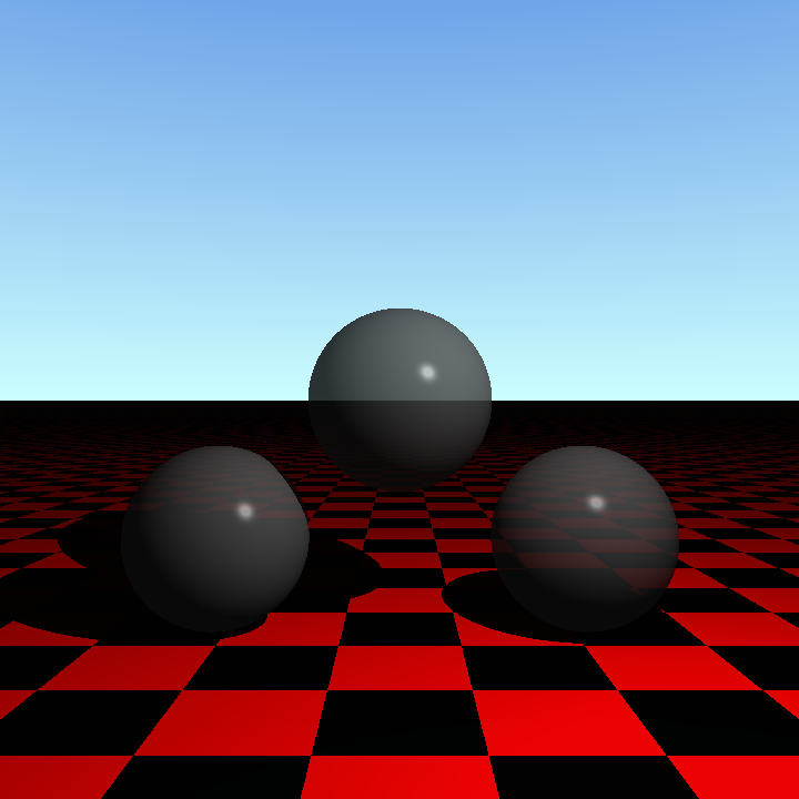
I accidentally added transmittance to the ray tracer when developing reflections; instead of using the reflected direction for the reflected ray I accidentally used the incoming ray's direction:

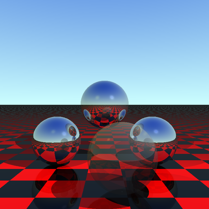
To add transmittance I've added a transmittance value to our materials, similar to reflectivity but instead describes the amount of light that passes through the object. We calculate the contribution to the overall colour from transmittance by tracing a ray into the object. When this ray intesects with the object again we have our exit point. Trace a ray back from this exit point through the scene as if it were a reflected ray to get the colour from transmittance. We can now add a partially transparent sphere to our scene:

However in real life when a light ray enters a transparent object it usually refracts to a new angle. The size of this refraction is governed by Snell's Law. This can be expressed in vector form as:
\[ \hat{\mathbf{R}} = r \hat{\mathbf{L}} + \hat{\mathbf{N}} (r c - \sqrt{1 - r^2(1 - c^2)}) \]
Where:
- \( \hat{\mathbf{R}} \) is the direction of the refracted ray.
- \( r \) is the ratio of refractive index of source material (\( r_s \)), i.e. the material the ray is currently inside, to the refractive index of target material (\( r_t \)), i.e. the material the ray is passing into. \( r = \frac{r_s}{r_t} \).
- \( \hat{\mathbf{L}} \) is the direction of incoming ray of light.
- \( \hat{\mathbf{N}} \) is the surface normal.
- \( c = - \hat{\mathbf{N}} . \hat{\mathbf{L}} \).
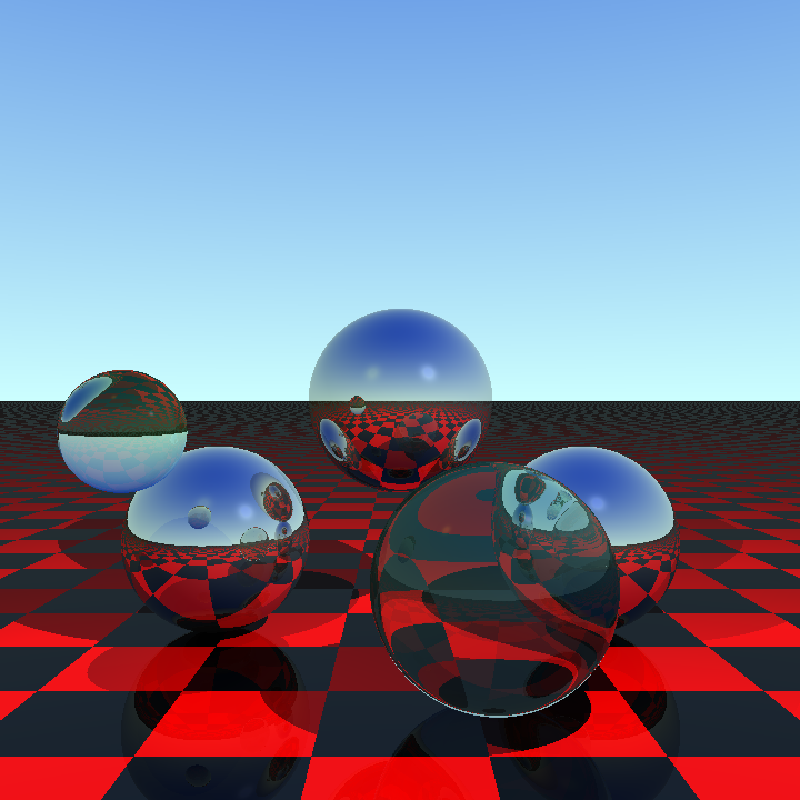
Taking this direction and the intersection point gives us our ray into the object. We then reuse the equation on the exit point with the refractive indices reversed, to find the direction of the exit ray. This gives us more realistic transparent spheres:

The sphere on the right has a low refractive index (1.05) so the light doesn't bend that much inside. The sphere on the left has a higher refractive index (1.33) that causes the light to bend enough to flip the image seen inside the sphere.
What if the value under the square root above was negative? Then we have total internal reflection - the ray does not transmit at all, but instead reflects. We can handle this in a simple way by not tracing the transmitted ray but instead add the amount of transmittance to the reflectivity and then proceeding with the reflection as normal.
To test total internal reflection I needed a new shape, a box.
Axis Aligned Box
The type of box I decided to add was an axis aligned box, i.e, one where the sides of the box lie along the three axes \( x \), \( y \) and \( z \). Whilst this is fairly restrictive to use in a scene it will be useful later on when to optimise things when we have more complex shapes to work out intersections for.
One way to calculate the intersection between a ray and a box is to use the slabs method. We think of the box as three overlapping slabs, where a slab is the space between the two parallel planes that make up opposite sides of the box.
For each slab we calculate the value of \( d \) from our ray equation \( \mathbf{R} = \mathbf{O} + d \hat{\mathbf{D}} \) that corresponds to the intersection with the near and far side. For each of the three axes we take the largest near intersection and the smallest far intersection. (If the ray is parallel to the axis then we just check it's origin in that axis fits inside the bounds of the box; if not it cannot intersect.) Then if the final near intersection has a greater value of \( d \) that the final far intersection the ray has missed the box. Also if \( d < 0 \) for the far intersection then both points are behind the origin of the ray and it misses the box. (Related to this - if \( d < 0\) for near but not far then the near point is behind the origin but not the far point, i.e. the ray starts inside the box.)
To ray trace the box we also need to find out exactly where on the box it hits. To do this we can plug our value of \( d \) (the near one unless the ray starts inside the box; then use the far one) to find the intersection point. One of the components of the intersection point must match one of the components for a side of the box - we can use this to work out which side and therefore the surface normal. The ray could intersect on an edge or corner of course - I have just returned the first normal found in this case rather than having the normal point out from the edge or corner.
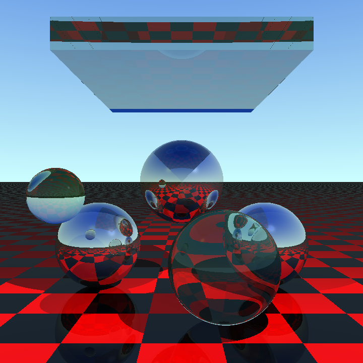
With all this we can now place a transparent box in the sky and get some total internal reflection:

A couple of things to note:
- The dark blue bar at the bottom of the box. Stepping through in the debugger this might actually be correct... For a light blue points on the left directly above the blue the ray from the camera is heading slightly left and upwards and strikes the bottom of the box. It refracts into the top of the box and heads out to the background towards the horizon. For the dark blue just below then the ray enters in a similar position but this time has moved just enough to refract into the back of the box instead it then leaves at a much steeper upward angle which sends it to a much darker blue part of the sky.
- The few erroneous dots. These are where the ray is hitting the edges - the normal is not quite correct and the ray ends up bouncing around inside the box until the recursion limit is reached, the ray tracer gives up and renders the point black. I've tried a few things to fix this (such as normals heading out at 45 degrees from the edges, or using a different edge) without much luck. I'm not going to worry about it for now however as I don't see axis aligned boxes ever really being using in a scene due to the restrictions around their alignment.
The code so far can be found on GitHub. There is more to do to make these materials look more realistic, such as changing the amount of reflection based upon viewing angle. However I'm bored with transparency for the moment so I'm going to move on to teapots instead...